Product Details:
|
Size: | 15mm*22mm(+25mm Antenna)*3.2mm | TX Power: | 13dBm |
---|---|---|---|
RX Sensitivity: | -124dBm | TX Current: | 25mA |
RX Current: | 5.5mA | Standby Current: | 1uA |
Antenna: | Helix Connector | Chipset: | CC1312 By Texas Instruments |
Frequency: | 434/868/915MHz | Reach: | 800m Max |
Working Tempurature: | -20~+70℃ | Working Voltage: | 1.8~3.8v |
Highlight: | TI CC1312R1F3 Sub GHz Module,Long Range Sub GHz Module,Cansec Wireless AN1312HA-E |
Cansec Wireless AN1312HA-A TI CC1312R1F3 Smart industry Long Range Sub-GHz Module
Parameter | Min | Typ | Max | Unit | |
Operating Voltage | 1.8 | - | 3.8 | V | |
Operating Temperature | -20 | - | +70 | ℃ | |
Current Consumption |
Sleep Mode | - | 1 | - | uA |
Receive mode | - | 8 | - | mA | |
Transmit Mode | - | 27 | - | mA | |
TX Power (For Carrier) | - | 12 | dBm | ||
RX Sensitivity (For Lora Modulation) | - | - | -121 | dBm | |
Distance |
434 / 470MHz:400-500 868 / 915MHz:600-800 |
m |
Cansec Wireless AN1312HA-A TI CC1312R1F3 Smart industry Long Range Sub-GHz Module
Description
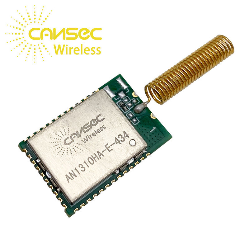
The AN1312 module is designed based on CC1312R. The CC1312R device is a Sub-1GHz wireless MCU targeting Wireless M-Bus, IEEE 802.15.4g, IPv6-enabled smart objects (6LoWPAN), KNX RF, Wi-SUN®, and proprietary systems, including theTI15.4-Stack.
The CC1312R device is a member of the SimpleLink™ MCU platform of cost-effective, ultra-low power,2.4-GHz and Sub-1 GHz RF devices. Very low active RF and microcontroller (MCU) currents, in addition to sub-μA sleep current with up to 80KB of parity protected RAM retention, provide excellent battery lifetime and allow operation on small coin-cell batteries and in energy-harvesting applications.
The CC1312R device combines a flexible, very low-power RF transceiver with a powerful 48-MHz Arm® Cortex®-M4F CPU in a platform supporting multiple physical layers and RF standards. A dedicated Radio Controller (Arm® Cortex®-M0) handles low-level RF protocol commands that are stored in ROM or RAM, thus ensuring ultra-low power and great flexibility. The low power consumption of the CC1312R device does not come at the expense of RF performance; the CC1312R device has excellent sensitivity and robustness (selectivity and blocking) performance.
The CC1312R device is a highly integrated, true single-chip solution incorporating a complete RF system and an on-chip DC/DC converter. Sensors can be handled in a very low-power manner by a programmable, autonomous
ultra-low power Sensor Controller CPU with 4KB of SRAM for program and data. The Sensor Controller, with its fast wake-up and ultra-low-power 2 MHz mode is designed for sampling, buffering, and processing both analog and digital.
Application
- 433-, 470- to 510-, 868-, and 902 to 928 MHz ISM and SRD Systems with down to 4 kHz of receive bandwidth
- Home and building automation
- Building security systems – motion detector, electronic door lock, door and window sensor, gateway
- HVAC – thermostat, wireless environmental sensor, HVAC system controller
- Fire safety systems – smoke detector, fire alarm control panel
- Video surveillance – IP camera
- Garage door openers
- Elevator and escalator control
- Smart grid and automatic meter reading
- Water, gas, and electricity meters
- Heat cost allocators
- Gateways
- Wireless sensor networks
- Long-range sensor applications
- Asset tracking and management
- Factory automation
- Wireless healthcare applications
- Energy harvesting applications
- Electronic Shelf Label (ESL)
Pad Number | Name | Pin Type | Description |
1 | GND | Ground Pin | Connect to GND |
2 | DIO_1 | Digital I/O | GPIO, |
3 | DIO_2 | Digital I/O | GPIO |
4 | DIO_3 | Digital I/O | GPIO |
5 | DIO_4 | Digital I/O | GPIO |
6 | DIO_5 | Digital I/O | GPIO, High drive capability |
7 | DIO_6 | Digital I/O | GPIO, High drive capability |
8 | DIO_7 | Digital I/O | GPIO, High drive capability |
9 | GND | Ground Pin | Connect to GND |
10 | VDD | Power | 1.8V to 3.8V main chip supply |
11 | DIO_8 | Digital I/O | GPIO |
12 | DIO_9 | Digital I/O | GPIO |
13 | DIO_10 | Digital I/O | GPIO |
14 | DIO_11 | Digital I/O | GPIO |
15 | DIO_12 | Digital I/O | GPIO |
16 | DIO_13 | Digital I/O | GPIO |
17 | DIO_14 | Digital I/O | GPIO |
18 | DIO_15 | Digital I/O | GPIO |
19 | JTAG_TMSC | Digital I/O | JTAG TMSC, High drive capability |
20 | JTAG_TCKC | Digital I/O | JTAG TCKC |
21 | DIO_16 | Digital I/O | GPIO, JTAG_TDO, High drive capability |
22 | DIO_17 | Digital I/O | GPIO, JTAG_TDI, High drive capability |
23 | DIO_18 | Digital I/O | GPIO |
24 | DIO_19 | Digital I/O | GPIO |
25 | DIO_20 | Digital I/O | GPIO |
26 | DIO_21 | Digital I/O | GPIO |
27 | DIO_22 | Digital I/O | GPIO |
28 | RESET_N | Digital input | Reset, active low. Internal pullup resistor |
29 | DIO_23 | Digital/Analog I/O | GPIO, analog capability |
30 | DIO_24 | Digital/Analog I/O | GPIO, analog capability |
31 | DIO_25 | Digital/Analog I/O | GPIO, analog capability |
32 | DIO_26 | Digital/Analog I/O | GPIO, analog capability |
33 | DIO_27 | Digital/Analog I/O | GPIO, analog capability |
34 | DIO_28 | Digital/Analog I/O | GPIO, analog capability |
35 | DIO_29 | Digital/Analog I/O | GPIO, analog capability |
36 | DIO_30 | Digital/Analog I/O | GPIO, analog capability |
37 | GND | Ground Pin | Connect to GND |
38 | ANT | RF_OUT | Antenna Type: NA RF_OUT |
39 | GND | Ground Pin | Connect to GND |
Note: The MCU IOC can map a number of peripheral modules such as GPIO,
SSI (SPI), UART, I2C, and I2S to any of the available I/Os.
The peripherals AUX and JTAG are limited to specific I/O pins.More information please reference Ti.com.
Contact Person: Sarolyn Kong